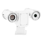
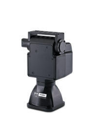
Teledyne FLIR PTU-D100 EX Pan-Tilt Unit
- Payloads 15lbs (std) to 25 lbs (ex)
- Top or Dual side mount available
- 360-continuous pan rotation
- Tilt position resolution down to 0.0075°
- Pan/tilt speeds up to 120° / Sec.
- Small form-factor
- Wide range DC voltage input
- Ethernet, RS-232 & RS-485
- IP67 Rated
Teledyne FLIR PTU-D100E
PAN/TILT UNIT FOR SIDE-MOUNTED PAYLOADS UP TO 25 LBS
The PTU-D100 E-Series supports any type of single or multi-part payload through a flexible bracketing system of top and/or side mounting. It has been designed to be simple to integrate. The PTU-D100 E-Series is an open platform that provides the flexibility needed while minimizing your development and integration effort. It has been proven in a wide range of mission-critical applications for positioning of cameras, lasers, antennas, or other instruments in both fixed and mobile environments.
Tough, Flexible, Programmable Pan/Tilt
HIGH PERFORMANCE WITH HEFTY PAYLOADS
With payload capacity up to 25 pounds and precise positioning, D100 pan/tilts have a wide range of pan speeds for smooth, precise 360° control.
RUGGED PRECISION POINTING
Precise, real-time control of position, speed, and acceleration — plus a rigid worm gear design — provides steady positioning in windy environments and vehicle-mounted applications.
POWERFUL PERFORMANCE
With integrated Ethernet and Web interfaces, increased command rates, reduced jitter, and advanced microstep control, D100 pan/tilts provide advanced performance at affordable prices.
The PTU‐D100 E Series is well suited for the following applications:
- Mid‐ and short‐range surveillance systems
- Automated detection and tracking
- Multi‐sensor perimeter monitoring systems
- Thermal and IR cameras
- Marine/shipboard sensor systems
- Harbor and port security
- Border security & law enforcement
- Highway & transportation monitoring
- Military special operations
- Satellite communications systems
- Microwave antenna systems (passive, active)
- Robotics & computer vision
| Pan Resolution | |
|---|---|
| Tilt Resolution | |
| Input Voltage |
12-30 VDC unregulated (fastest performance and torque @ 30 VDC) |
| Power Consumption | |
| Payload Mounting | |
| Slipring | |
| Weight | |
| Interface Controls | |
| Wiring Configuration |
PL01, PL02, PL17 pass-through wiring options. 100BaseT wiring option with PL17 |
| Operating Temperature | |
| Standards | |
| ECCN Code |
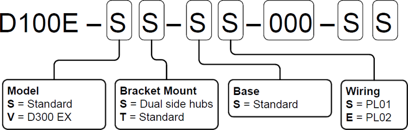
Each PTU‐D100 E series unit includes a model number that is located on the base of the unit. This number lists the options present on that particular unit.
Different options may require specialized instructions, and this section will help to choose the appropriate configuration.
The PTU‐D100 E series model number appears as follows:
The following configuration and options are available for the PTU‐D100E:
- EX Gears: The PTU‐D100E with EX gears provides additional torque with slower axis speeds for heavier loads.
- Bracket Mount: Payloads can be mounted on the top and/or side. A number of bracket options are available to suit each application.
- Bottom Base Connector: The PTU‐D100E can be configured with the base connector located on the bottom of the unit, which is useful for pole‐mounted applications.
- Slip Ring: The PTU‐D100E is available with or without a slip ring for continuous 360° panning.
- Wiring: Different payload pass‐through wiring options are available for passing signals through the PTU to the payload.
- Range of Motion: If needed, you may request special limits.
EX Gears
The PTU‐D100E with EX gears increases the maximum payload rating from 15 lbs. to 25 lbs. by providing additional torque at reduced axis speeds.
Part Number: D100E‐V_‐__‐000‐SS (D100E‐EX gears)
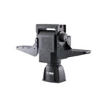
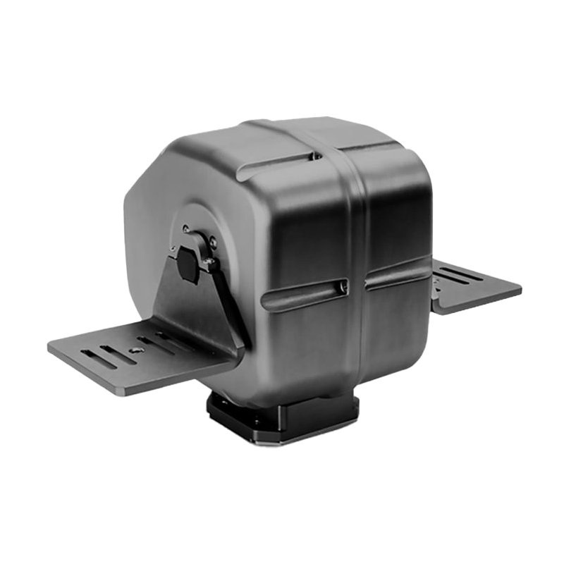
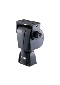
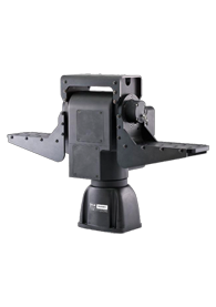
Bracket Mount
The PTU‐D100E accepts payloads using top or side mounting. Side mounting offers the higher payload rating because it reduces tilt axis torque.
The PTU‐D100E itself can be mounted in any orientation; however, consideration should be given to gravity and torque effects depending on PTU orientation and payload mounting orientation and balance.
Top Mount
PTU‐D100E with a top‐mount configuration and included top bracket -
Part Number:D100E‐_T‐__‐000‐__ (Top Mount)
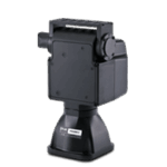
PTU‐D100E with one side‐mount bracket -
Part Number:
D100E‐_S‐__‐000‐__
plus one bracket:
D100‐BKT‐LSTD (qty.)
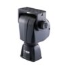
PTU‐D100E with two side‐mount brackets -
Part Number:
D100E‐_S‐__‐000‐__
plus two brackets :
D100‐BKT‐LSTD (qty. 2)
PTU‐D100E with a top bracket and one or two side brackets -
D100E‐_T‐__‐000‐__ (Top Mount)
plus one bracket :
D100‐BKT‐LSTD (qty. 1) or two brackets : D100‐BKT‐LSTD (qty. 2)
Bottom Base Connector
Slip Ring
Payload Wiring
PTU‐D100E units equipped with an internal slip ring are available with internal pass‐through wiring, which provides a 19‐pin MIL‐C‐26402 female receptacle at the top of the PTU near the payload location to connect video, power, and other signals. (The mating connector is provided to facilitate cable construction if needed.) These signals then pass through the PTU, into the connector at the base of the unit, and the cable harness (if purchased). This option allows you to reduce the amount of external cables and eliminate potential damage to external cables.
- The payload receptacle contains lines for Video 1, Video 2, payload power, and general pass‐through lines.
- The base receptacle contains lines for Video 1, Video 2, payload power, general pass‐through lines, PTU control (RS‐232, RS‐485), and PTU power.
PL01 Wiring
PL01 allows you to route signals to the payload as shown in the table via 10 dedicated conductors. A mating connector for cable construction is included.
Part Number: D100E‐__‐_S‐000‐__
PL02 Wiring
PL02 allows you to route signals to the payload as shown in the table on the previous page via 13 dedicated conductors. A mating connector for cable construction is included.
Part Number: D100E‐__‐_E‐000‐__
PL17 Wiring
PL17 gives you the maximum number of conductors for signals to be routed from the base of the pan tilt to the payload connector. A mating connector for cable construction is included.
Part Number: D100E‐__‐_Q‐000‐SS
Range of Motion
The PTU‐D100E has the following standard factory pan and tilt axis limits. Factory limits define the range of motion allowed for an axis when limits are enabled, and that axis cannot travel beyond those limits.
The PTU‐D100E also includes a slip ring that allows continuous 360° pan‐axis movement.Pan Range Options
Part Number: D100E‐__‐__‐000‐S_ (std.)
Tilt Range Options
Part Number: D100E‐__‐__‐000‐SS (std)
TILT‐RANGE‐180 (+/‐ 90° tilt)- PTU-5
- D48E
- D100E-EX*
- D300E
- D300E-HS
- D300E-EX
Mounting Options |
PTU-5
|
D48E
|
D100E-EX*
|
D300E
|
D300E-HS
|
D300E-EX
|
Top Mounting Brackets (TMB) |
Included | TMB incl. w/ D48E-SS No TMB PN: D48E-SN | TMB not incl. w/ D100E-SS TMB PTU PN: D100E-ST | Top Bracket not incl. w/ D300E-SS Top Bracket PTU PN: D300E-SD | Top Bracket not incl. w/ D300E-SS Top Bracket PTU PN: D300E-SD | Top Bracket not incl. w/ D300E-SS Top Bracket PTU PN: D300E-SD |
Top Payload Capacity |
5 lbs / 2.2 kg | 10 lbs / 4.5 kg | 25 lbs / 11.4 kg | 35 lbs / 15.9 kg | 25 lbs / 11.3 kg | 60 lbs / 27.2 kg |
Side Mounting Brackets (SMB) |
1 or 2 SMBs can be purchased & installed | 1 or 2 SMBs can be purchased & installed | 1 or 2 SMBs can be purchased & installed | Only 1 SMB can be installed on the standard D300E-SS 1 or 2 SMBs can be installed on the D300E-SD | Only 1 SMB can be installed on the standard D300E-SS 1 or 2 SMBs can be installed on the D300E-SD | Only 1 SMB can be installed on the standard D300E-SS 1 or 2 SMBs can be installed on the D300E-SD |
Side Payload Capacity |
6 lbs / 2.7 kg | 15 lbs / 6.8 kg | 25 lbs / 11.4 kg | 70 lbs / 31.8 kg | 40 lbs / 18.1 kg\ | 90 lbs / 40.8 kg |
TOTAL PAYLOAD CAPACITY |
The combined weight of top and side payloads (if using both) cannot exceed the side payload capacity rating | The combined weight of top and side payloads (if using both) cannot exceed the side payload capacity rating | The combined weight of top and side payloads (if using both) cannot exceed the side payload capacity rating | The combined weight of top and side payloads (if using both) cannot exceed the side payload capacity rating | The combined weight of top and side payloads (if using both) cannot exceed the side payload capacity rating | The combined weight of top and side payloads (if using both) cannot exceed the side payload capacity rating |
BRACKET NOTES |
Top & side brackets cannot be used together -- the bracket clamp allows only one type at a time | - | D100E-ST bracket numbers are slightly different: D100-BKT-S | - | - | - |
| View | View | View | View | View | View |